Hi Tectu
Awesome board! I am see open hardware logo on it. What tools you have used to create schematic, topology and impedance calculation. Are that tools open too? What IC will use SRAM (STM32 or FPGA)?
Post your PCB
Re: Post your PCB
Hello Barthess,
Here are the tools that I used:
The SRAM is only used by the STM32. It's used to accelerate the GUI (cache decoded images, buffer the graph data and so on).
~ Tectu
Here are the tools that I used:
- KiCAD - Schematics, PCB design, Calculations
- GNU ARM GCC - Compiler, Linker and Debugger for ARM software
- Make - Build system
- iceCube2 - FPGA design software
- ChibiOS/RT - Runs on the STM32 to control everything
- µGFX - To create the optional GUI on the touchscreen
barthess wrote: What IC will use SRAM (STM32 or FPGA)?
The SRAM is only used by the STM32. It's used to accelerate the GUI (cache decoded images, buffer the graph data and so on).
~ Tectu
Re: Post your PCB
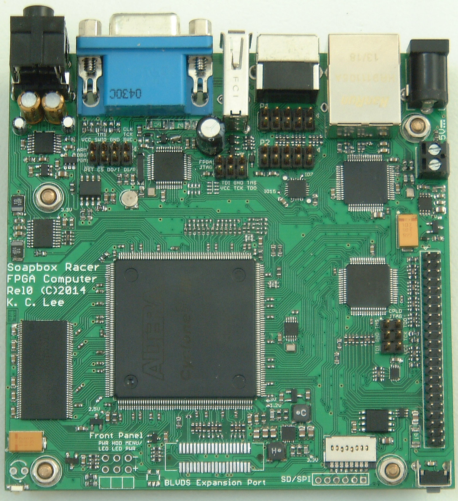
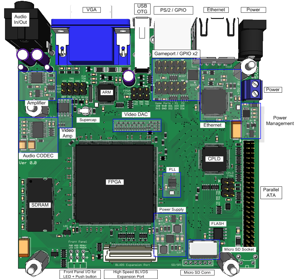
Here are some pictures of my PCB for a FPGA Computer/Eval board. (work in progress)
I am working on firmware right now. I am using a Freescale Kinetis K22 and using ChibiOS 2.6.5. I have been trying to back port some of the new code. Not having much luck with serial port. I'll have to come back to that later as it s not critical to the project.
Actually PCB:
https://static.hackaday.io/images/34236 ... 727597.jpg
Rendered PCB with text:
https://static.hackaday.io/images/44226 ... 019001.png
Project page:
https://hackaday.io/project/1347-FPGA-C ... Eval-board
Re: Post your PCB
Now, that is a rather interesting PCB. Any way to get one? What's the lead price?
Also, are Atel tools freely available? (Also on Linux?)
~ Tectu
Also, are Atel tools freely available? (Also on Linux?)
~ Tectu
Re: Post your PCB
Tectu: Not sure if you are talking about my PCB or someone else, but I might as well add more details.
It is first revision prototype right now. Part cost + PCB is below $200 US. 10 pieces of bare double sided proto PCB done in China for about $21 including shipping.
Took one and half days for me to hand solder, hot air the DFN parts and reflow in toaster oven. I had to stop a few times because my neck was getting sore. It was an expensive gamble, but I pulled it off. Life would have been easier if I pay extra $20 for a stencil and $15 for some good quality solder paste, but I can't justify for that. Not sure if there will ever be volume to justify a small production run as the production charges + part cost + PCB CAD tool commercial license upgrade can get very expensive. There are FPGA development boards with much better specs at those price range. I'll never the motivation to actually do anything with them.
My Schematic/PCB design is done in Eagle CAD. Unfortunately the size & complexity, so it can be viewed, but not saved under their free tool license. Even if you can, not much you can change without redoing the whole layout. I did 15 design/layout revisions to get things to fit in that board dimension for the PCB deal. Also did a lot of 3D modeling with a free tool afterward to check footprint, layout etc. That work seems to pay off as there is one mistake on the board I found so far that would require some minor mod.
Non open source, but $0.00 tools FPGA tools for Xilinx CPLD and Altera FPGA are available under Windows and Linux. Haven't gone that far yet as I am playing with ChibiOS right now. My first time working with ARM chips and tool chain.
It is fun to force and push myself outside my comfort zone once in a while.
It is first revision prototype right now. Part cost + PCB is below $200 US. 10 pieces of bare double sided proto PCB done in China for about $21 including shipping.
Took one and half days for me to hand solder, hot air the DFN parts and reflow in toaster oven. I had to stop a few times because my neck was getting sore.
My Schematic/PCB design is done in Eagle CAD. Unfortunately the size & complexity, so it can be viewed, but not saved under their free tool license. Even if you can, not much you can change without redoing the whole layout. I did 15 design/layout revisions to get things to fit in that board dimension for the PCB deal. Also did a lot of 3D modeling with a free tool afterward to check footprint, layout etc. That work seems to pay off as there is one mistake on the board I found so far that would require some minor mod.
Non open source, but $0.00 tools FPGA tools for Xilinx CPLD and Altera FPGA are available under Windows and Linux. Haven't gone that far yet as I am playing with ChibiOS right now. My first time working with ARM chips and tool chain.
It is fun to force and push myself outside my comfort zone once in a while.
Re: Post your PCB
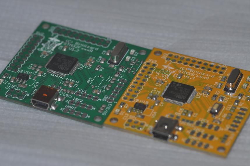
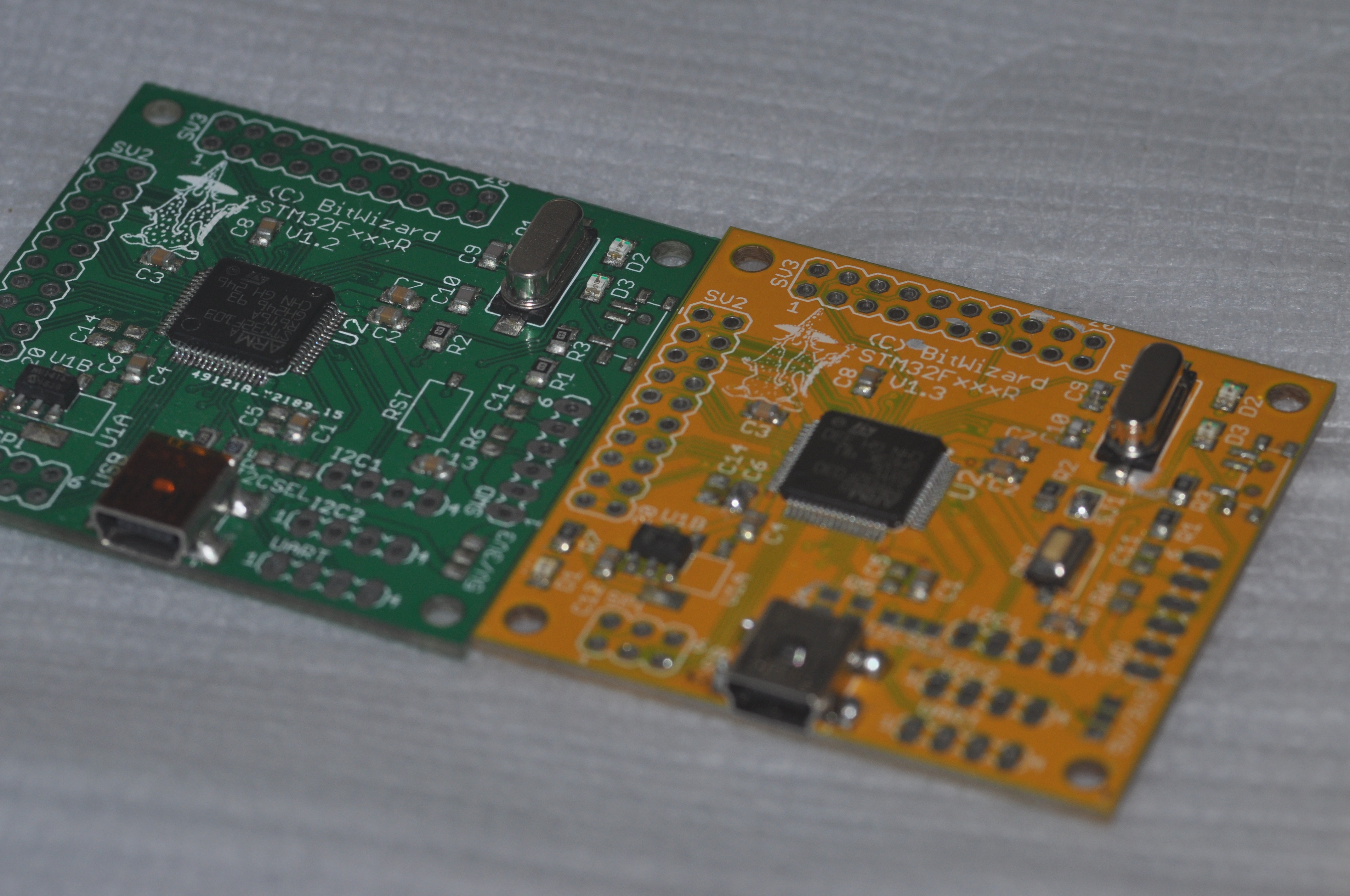
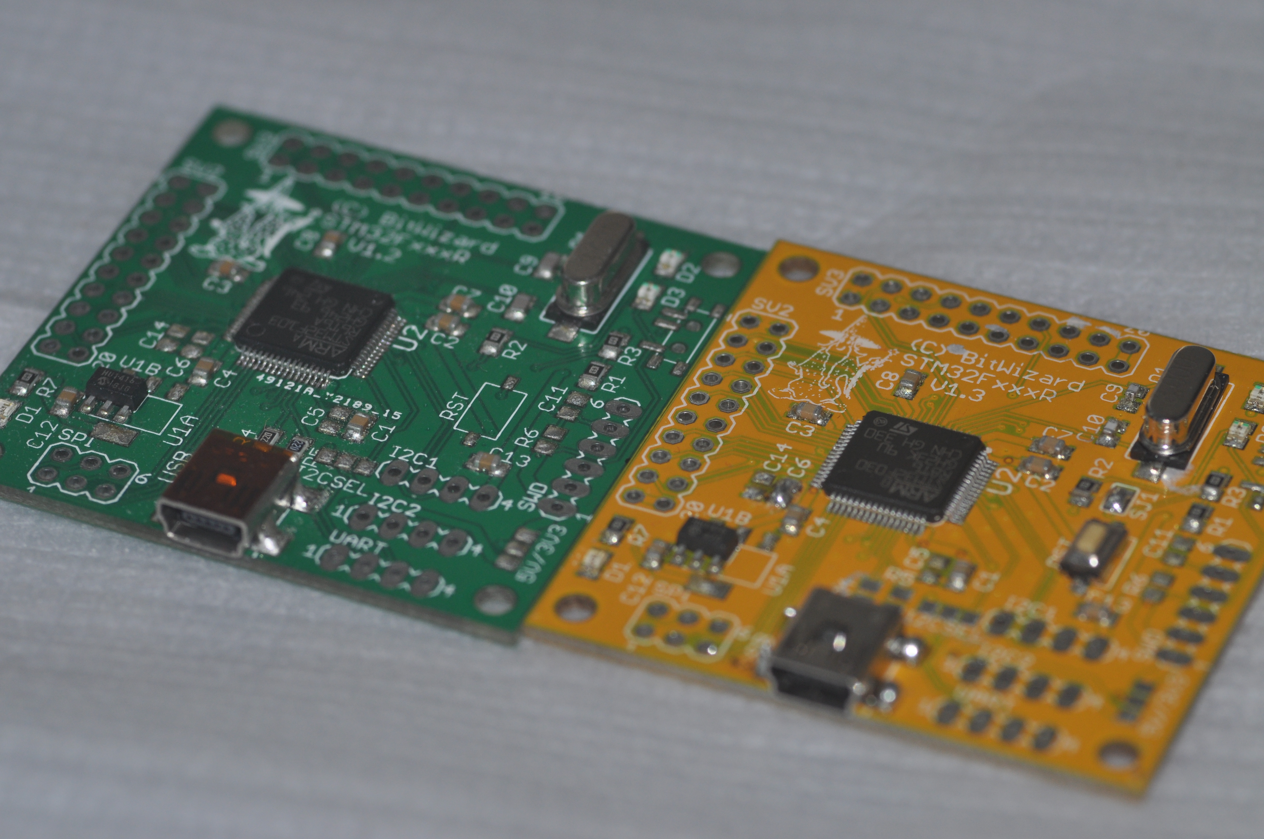
Barthess asked me to post my PCB here...
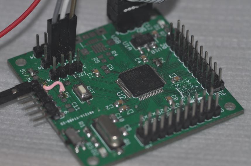
The two boards that volunteered for the photoshoot didn't have their throughole pins mounted. The last image is of a board that DOES have them. That last board doesn't have the USB connector mounted, which means it's tricky to feed it power. Since then even when the CPU doesn't do USB I mount the USB connector for easy power....
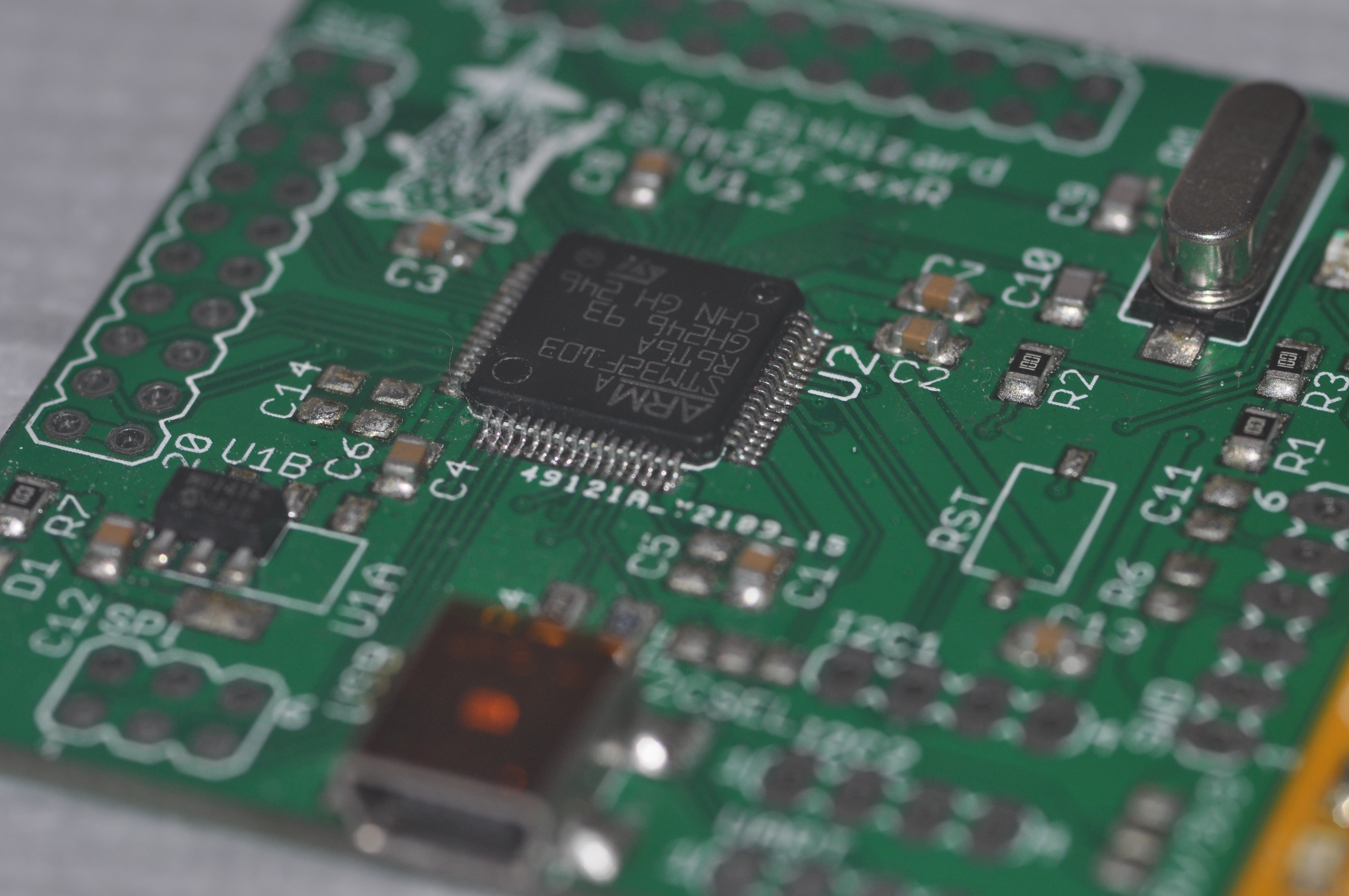
Hmm. When the '103 board pictured was assembled, I had never used the reset button on these boards, so I didn't mount it.
The board can handle about 20 different STM32 CPUs. About five or so have been tested. 030, 072, 103, 205, 303, 405. Six it seems. Maybe more.
So there goes:


Click on the images for the full-res monsters.
The two boards that volunteered for the photoshoot didn't have their throughole pins mounted. The last image is of a board that DOES have them. That last board doesn't have the USB connector mounted, which means it's tricky to feed it power. Since then even when the CPU doesn't do USB I mount the USB connector for easy power....
Hmm. When the '103 board pictured was assembled, I had never used the reset button on these boards, so I didn't mount it.
The board can handle about 20 different STM32 CPUs. About five or so have been tested. 030, 072, 103, 205, 303, 405. Six it seems. Maybe more.
So there goes:

Click on the images for the full-res monsters.
-
russian

- Posts: 364
- Joined: Mon Oct 29, 2012 3:17 am
- Location: Jersey City, USA
- Has thanked: 16 times
- Been thanked: 14 times
Re: Post your PCB
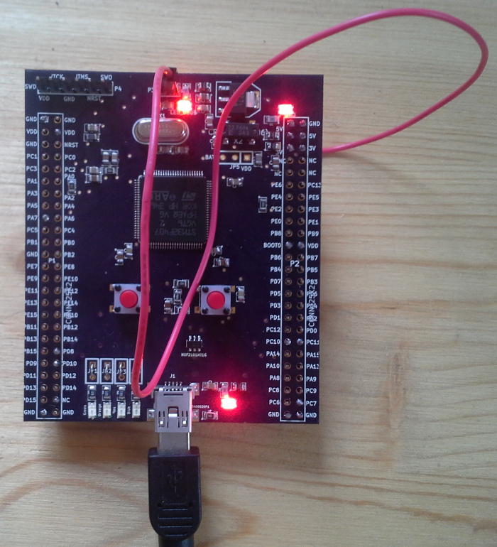
this one is pin-compatible with stm32f4discovery
KiCad sources:
https://svn.code.sf.net/p/rusefi/code/t ... ain_board/
Does anyone have any KiCad projects with a 155 or 176 pin stm32 chip?
Who is online
Users browsing this forum: No registered users and 9 guests